(E) Joining a Micro-Part
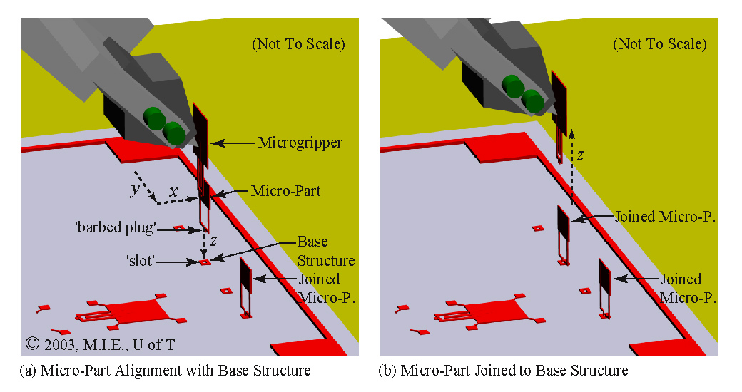
After orienting the distal arm to the joining orientation, as shown in Fig. 7(b), the video microscope is positioned above the microgripper using the microscope three-axis translation stage. The microscope is focused down on the snap-lock 'barbed plug' of the perpendicular micro-part. With the barbed plug in-focus, the micro-part is aligned in the x and y axes with the 'slot' located on the base structure, as shown in Fig. 9(a). When the alignment is deemed good, the distal arm is commanded down in the z-axis. The insertion of the barbed plug into the slot can be observed using the video microscope. Next, the distal arm is commanded back up in the z-axis, which causes the microgripper to release the micro-component, as shown in Fig. 9(b). The micro-component remains joined perpendicularly to the base structure.