(D) Manipulation of a Micro-Part
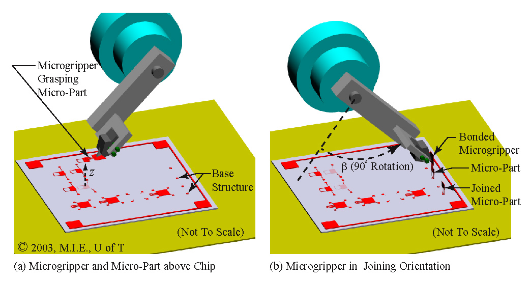
After the microgripper has grasped a micro-part and broken the tethers that hold it, the micro-part will be free from the substrate. The distal arm is commanded up along the z-axis, as shown by the dashed arrow in Fig. 7(a). In order to join the micro-part perpendicularly to the substrate, the distal arm is rotated 90 degrees counter clockwise about the beta-axis, as shown in Fig. 7(b). Note that in this new orientation, the contact head is again 45 degrees below the horizontal, although the microgripper and the micro-part are now perpendicular to the substrate. Also, note that the micro-part (held by the microgripper) is the lowest point on the distal arm. In this orientation, the microgripper is able join the micro-part to the 'base structure' (Fig. 9(a)) on the substrate using a snap-lock joint.
.jpg)