|
|
|
|
|
 |
|
 |
|
|
|
(B) Bonding to a Microgripper
|
|
| Solder Bonding a Microgripper to the MJMP:
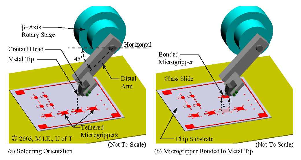
Before any microassembly operations can be performed, a microgripper must be bonded to the MJMP. A device referred to as the contact head is bolted to the distal arm of the MJMP and acts as the interface between the microgripper and the MJMP. A close up view of the contact head, the distal arm and the MEMS chip is shown in Fig. 2(c). Fig. 3 illustrates a representation of the same configuration, however, the various elements are not drawn to scale. The contact head operates like a custom designed soldering iron, and is heated to temperatures that can melt tin/lead solder. A built in thermocouple and external temperature controller regulate the temperature of the contact head during solder bonding. The contact head has a small copper metal tip protruding from the bottom, to which the microgripper is bonded.
|
|
 |
|
| Figure 3. Illustration of Solder Bonding Procedure [CLICK TO ENLARGE] |
|
|
| The microgripper is attached to the chip substrate by tethers, as shown in Fig. 3(a). The tethers are attached to anchor pads, which are permanently attached to the substrate. The tethers are designed to be strong enough to hold the microgripper onto the substrate during transportation of the chips. They also immobilize the microgripper during the solder bonding operation.
To create a solder bond, the distal arm is first oriented 45 degrees below the horizontal, as shown in Fig. 3(a). In this orientation, the metal tip of the contact head is the lowest point of the distal arm assembly, and can make contact with the microgripper. This orientation ensures that the other larger elements of the MJMP, such as the distal arm, or the beta-axis rotary stage, do not interfere with the chip substrate due to their relatively large size. This orientation also allows the metal tip to be in direct view of the video microscope system.
|
|
.JPG) |
|
| Figure 4. SEM Images of Microgripper Solder Bonded to Metal Tip of Contact Head [CLICK TO ENLARGE] |
|
| To make a solder bond, the contact head is heated to 300 degrees C and held at that temperature for about 20 minutes to allow the entire distal arm assembly to reach thermal equilibrium. While the contact head is hot, the metal tip is localized with respect to the target microgripper. After localization, the distal arm is temporarily positioned away from the substrate chip to allow the operator to apply tin-lead solder to the heated metal tip. While the solder remains molten, the metal tip is re-aligned with the microgripper, and pressed down against it. The metal tip is then allowed to cool. During the cooling process, the solder solidifies and forms a bond between the metal tip and the microgripper. As the distal arm cools, it thermally contracts causing the bonded microgripper to be pulled away from the substrate, thereby causing the tethers to break away and freeing the microgripper from the substrate. After a completed solder bonding operation, the distal arm is commanded up along the z-axis, as shown by the dashed arrows of Fig. 3(b). Solder bonding allows the contact head to be electrically and mechanically joined to the microgripper. In addition, should the microgripper become damaged, the solder is re-melted, the old microgripper is brushed away, and a new microgripper is solder bonded. Fig. 4(a) and Fig. 4(b) show two SEM (scanning electron microscope) images of a successful solder bond with a microgripper.
A video movie of the solder bonding operation is available for viewing.
|
|
|
|
|
|
|
|
|